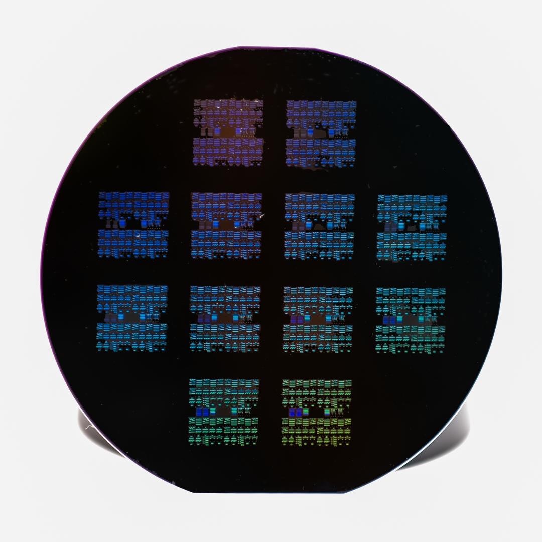
O/C Band 145 GHz Ring Resonator Modulator
RRM-C145
Key Features
-

3-dB electro-optic bandwidth >145 GHz
-
 Lumped, low-capacitance RF design
 -

Chip dimensions 1.5 mm x 2 mm
-

O/C band operation
-

Possible electrical drive: Single, differential, or dual
-
 Available as single, 4-channel or 8-channel device
Description
The RRM-C145 Ring Resonator Modulator uses a resonant structure to generate intensity modulation with excellent performance. It achieves stable operation beyond 145 GHz—and tests have shown functionality up to 170 GHz. This makes it a solid choice for engineers building next-generation optical systems.
Importantly, the RRM-C145 doesn’t require a bias voltage source. Instead, users can simply tune the laser wavelength to adjust the operating point. This approach simplifies integration and saves valuable board space.
You can order the RRM-C145 as a bare chip or in a semi-packaged format. In both cases, Polariton ensures mechanical compatibility and thermal stability.
Related Papers
Variants & Specifications
Polariton is offering this device in various variants, being single, quad and octo channel, ideal for a wide range of optical interconnect solutions.
| EO bandwidth | Optical band | RR variant | Ordering code |
| 145 GHz | O band | single-ended, differential, dual | RRM-C145-o |
| 145 GHz | C band | single-ended, differential, dual | RRM-C145-c |
(1) A probable 4-channel version with GSG probes for GS operation is available on demand.
Performance Specifications
| O band | C band | |
| Peak wavelength | 1310 nm | 1550 nm |
| Insertion loss (IL) | <10 dB | <8 dB |
| Static extinction ratio (ER) | >8 dB | >8 dB |
| DC bias on/off voltage | <1.5 V | <1.5 V |
| 3-dB EO bandwidth | >145 GHz | >145 GHz |
| Vdrive @ 100 kHz, @ 50 Ohm* | <2 V | <2 V |
| Free Spectral Range | ~4.7 nm | ~4.7 nm |
Maximum Ratings
| O band | C band | |
| Optical input power** | Contact Polariton | 7 dBm |
| RF input power @ 50 Ohm | 18 dBm | 18 dBm |
| DC voltage at RF input | 0 V | 0 V |
| DC bias voltage DC bias current | 2.5V 15 mA | 2.5V 15 mA |
| Operating / storage temperature | ~25 °C | ~25°C - 50 °C |
* Plasmonic modulators are high-impedance devices. Twice the voltage provided by a 50-Ohm signal source will drop across the plasmonic modulator.
Using a DC source or a high-impedance-matched driver, double the voltage is required to switch the modulator from the on to the off state.
** Based on reliability data for 500 h at 50°C and 9 dBm input power with a Vп degradation < 10%.
Mechanical and Optical Specifications
| O band | C band | |
| Optical input and output | Grating coupler (GC), 127 um pitch | Grating coupler (GC), 127 um pitch |
| Center wavelength at GC angle | 1310 nm at 8° | 1550 nm at 8° |
| Optical source needed | Tunable laser source,1310 nm ±10 nm range | Tunable laser source,1550 nm ±10 nm range |
| Electrical RF interface | G-S, S-G, S-S̄, S̄-S, or S1-S2, 30 –170 μm pitch | G-S, S-G, S-S̄, S̄-S, or S1-S2, 30 –170 μm pitch |
| Electrical DC interface | +/-, 75 – 245 μm pitch | +/-, 75 – 245 μm pitch |


